Shell and Tube Heat Exchanger Numerical Study, Industrial Application
۲,۷۰۰,۰۰۰ تومان تخفیف دانشجویی
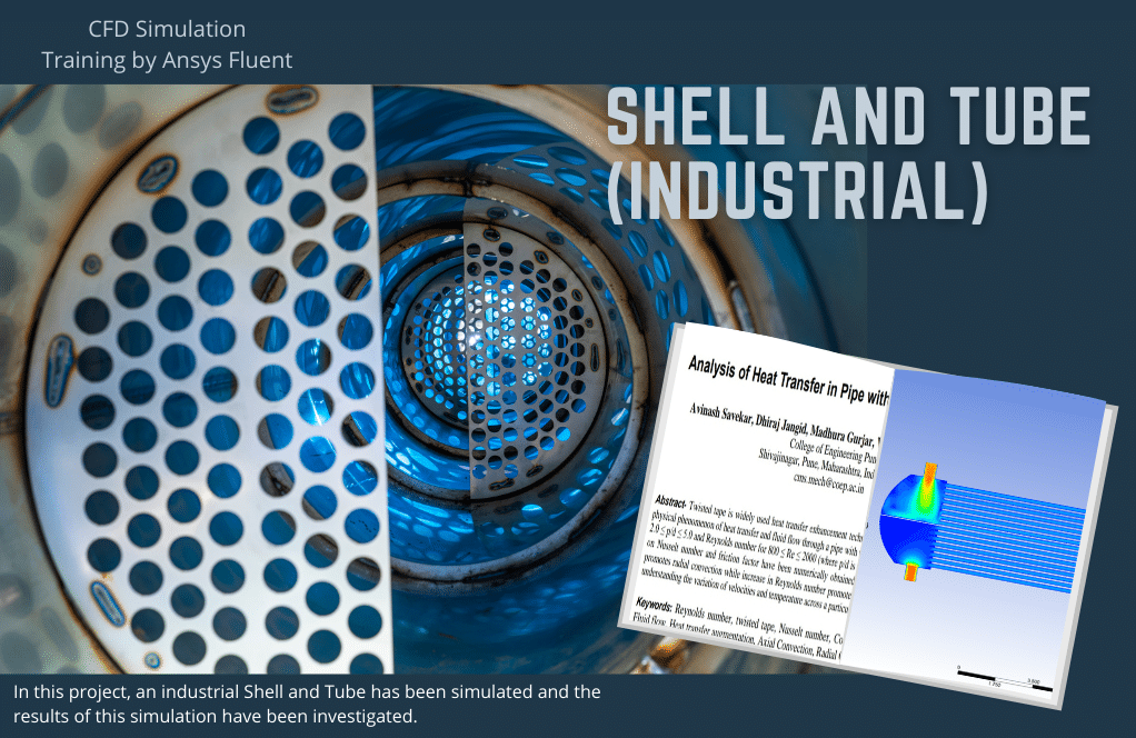
In this project, an industrial Shell and Tube has been simulated and the results of this simulation have been investigated.
This product includes Geometry & Mesh file and a comprehensive Training Movie.
There are some free products to check our service quality.
To order your ANSYS Fluent project (CFD simulation and training), contact our experts via [email protected], online support, or WhatsApp.
بر روی افزودن به سبد خرید کلید کرده و فایل های هندسه، مش و فیلم آموزشی جامع را دریافت کنید.
برای سفارش پروژه خود و یا بهره مندی از مشاوره رایگان، با کارشناسان ما از طریق ایمیل ([email protected])، پشتیبانی آنلاین و یا واتس اپ (09126238673) در ارتباط باشید.
برای کنترل کیفیت خدمات ما میتوانید از محصولات رایگان استفاده کنید.
توضیحات
Purpose
One of the most applications of shell and tube is in refineries. In refineries, the temperature of the oil is raised to remove impurities. After the impurities are separated from the oil, it is inserted into the shell and tube to lower the oil temperature to enter the barrel. The boiling temperature of the oil in this case study is 548 k. The oil should enter the shell and tube.
Meanwhile, its temperature decreases slightly and enters the shell and tube with a 540 k. Our goal in designing this shell and tube is to decrease the oil temperature to at least 40 degrees to get the oil into the barrel. The barrel material is such that the temperature of the fluid entering should not be more than 500 degrees (Kelvin) to prevent the shape from deforming.
Abstract
As mentioned earlier, this project aims to reduce the temperature of the oil. Shell and tube heat exchanger is a class of heat exchanger designs. It is the most common type of heat exchanger in oil refineries and other large chemical processes and is suited for higher-pressure applications. As its name implies, this type of heat exchanger consists of a shell (a large vessel) with a bundle of tubes inside it. One fluid runs through the tubes, and another fluid flows over the tubes (through the shell) to transfer heat between the two fluids. In this project, Ansys Fluent software stimulated an industrial shell and tube. After simulating the present shell and tube, it was observed that this heat exchanger has the efficiency required in refineries.
Introduction
The original shell and tube exchangers design was presented in the early 1900s to fulfill the power plants’ requirements for large heat exchangers such as condensers and feedwater heaters mightly apply in high pressures. These basic usages of shell and tube heat exchangers go on to be applied, but the models have become specialized and sophisticated. The industrial application of shell and tube heat exchangers known today also started in the 1900s to incorporate the needs of the oil industry. Oil heaters, coolers, reboilers, condensers for various crude oil fractions, and related organic liquids were required for rugged outdoor service, often dirty fluids, and high temperatures and pressures.
How the device works
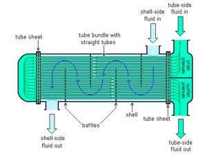
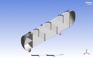
According to the figure below, one fluid passes through a set of tubes, all connected to an inlet and outlet, and the other fluid at a different temperature inside the shell where the tubes are located. Thus, heat is transferred from hot fluid to cold fluid due to the temperature difference between the two fluids and through the walls of the tubes. Thus, heat transfer takes place between the two fluids via indirect contact. This heat exchanger is widely used in different industries and for different fluids. As you can see in the figure below, one of the hot or cold fluids enters a bunch or row of tubes and goes to the end of the heat exchanger and rotates 180 degrees again into another row of tubes. At the same time, another fluid of different temperatures enters the shell through a duct and begins to move around the tubes. Obstacles called baffles are embedded in the fluid path in the shell to give the fluid inside the shell a turbulent motion to transfer more heat between the two fluids. The top and bottom of the tube are held by a piece called a tube sheet. In addition to holding the tubes, the tube sheets also perform a sealing operation so that the two fluids do not have physical contact with each other.
Advantages of shell and tube heat exchanger
- 1. Suitable for high-pressure applications.
- Easy maintenance, service, and replacement of parts.
- Flexibility in reducing or increasing capacity by reducing or adding tubes.
Disadvantages of shell and tube heat exchangers
- Limitation on heat transfer rate due to low heat transfer surfaces between two fluids
- The flow type is only heterogeneous and can not be used perpendicular to each other.
- Increasing the number of parallel pipes and connecting them with flanges increases the possibility of leakage in the joints.
- Its construction cost for high heat transfer increases significantly.
Simulation
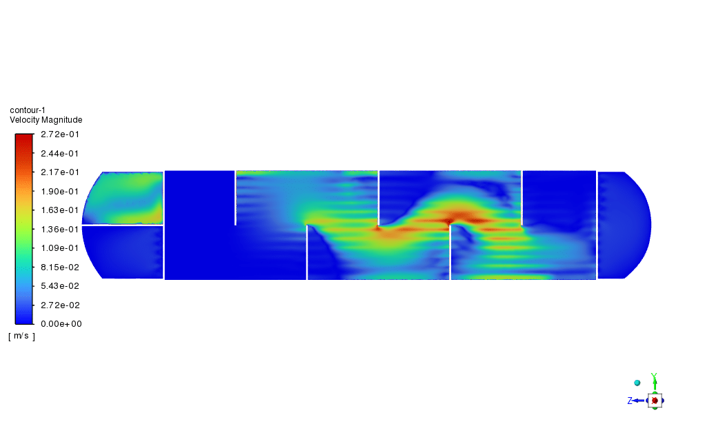
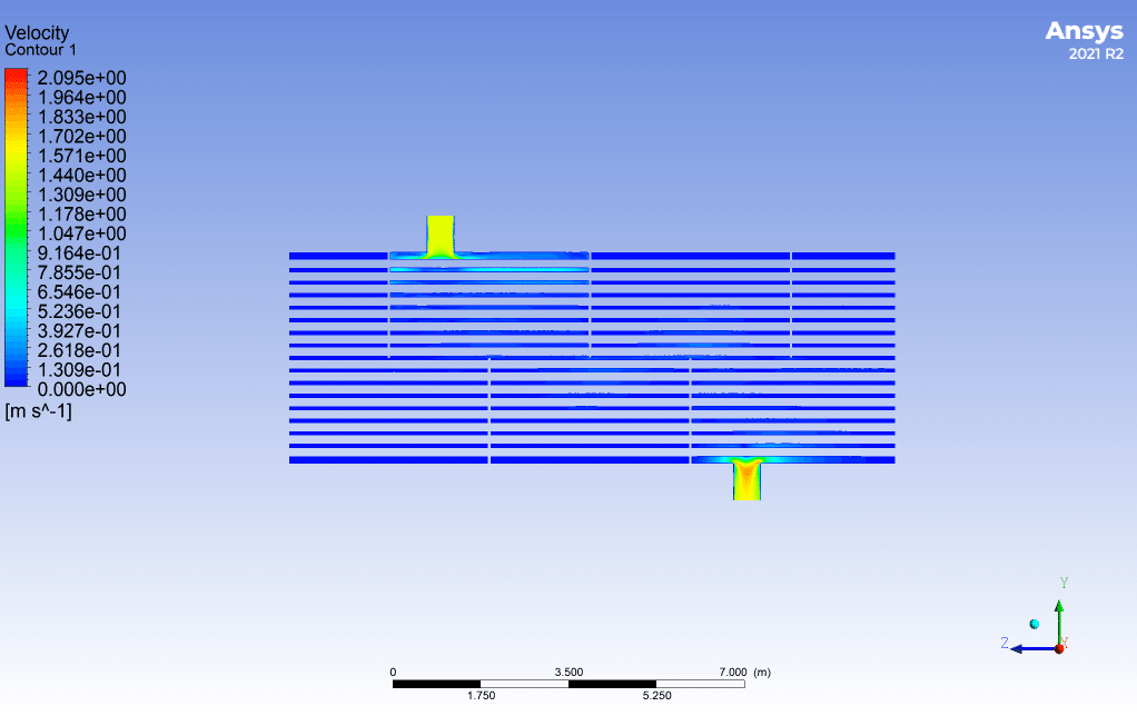
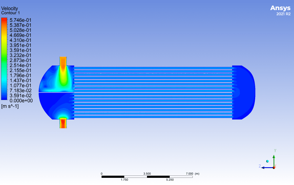
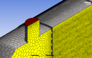
We designed the geometry of the present work by Spaceclaim software. To design this shell and tube, the TEMA standard has been used. We use the B-type for the front end stationary Head Type; in addition, we use the E-type for the shell, and for Rear-end head, we use something like P-type. So, the shell and Tube type is BEP. We chose SQUARE standard tube patterns to install the tube in the shell. Also, the type of transverse baffles is horizontal. The meshing of this present model has been generated by Ansys Meshing software. The mesh grid is structured, and the total cell number is more than 29000000. So, for the decreasing computational costs, use the polyhedral mesh, which reduced the number of meshes to 6460581. Shell and tube simulations are performed steadily with the energy equation, and the k-ε model is standard as the turbulence model. The fluids used in this simulation are water inside the shell and oil inside the tube. Coupling of velocity and pressure equations is also performed using the SIMPLE algorithm.
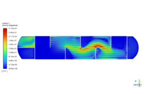
Shell and Tube Results
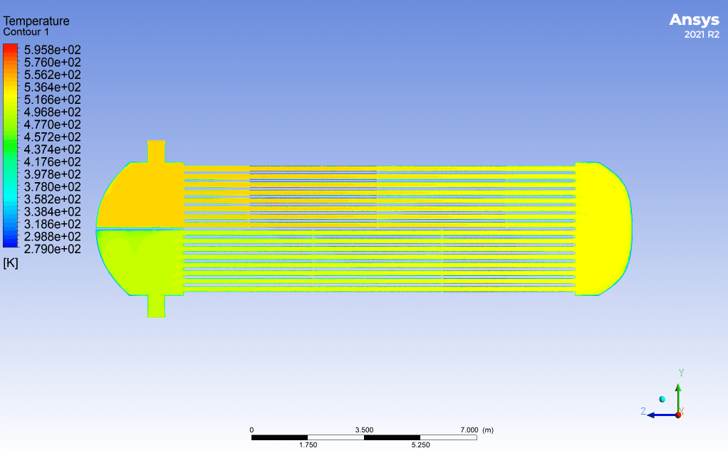
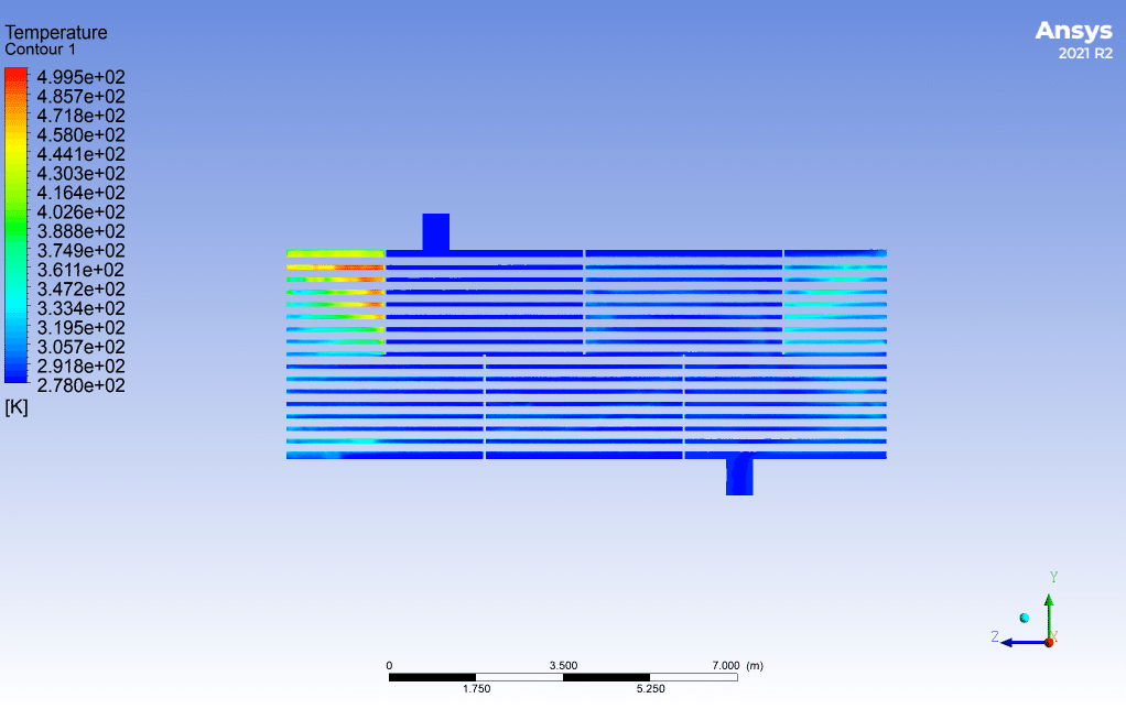
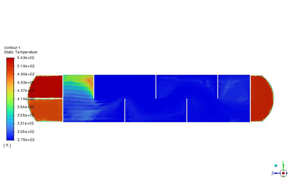
According to the design done using the TEMA standard, the outlet temperature of the tube is less than 500 k, and we have reached our goal.
| zone | Inlet Temperature | Outlet Temperature |
| shell | 278 | 282.5145 |
| Tube | 540 | 495.22479 |
Suggestion
Suppose the required temperature in another case study is much lower than the obtained value. Several shells and tubes can be used by setting the outlet temperature of the tube, considering various configurations and operating conditions.
You can obtain Geometry & Mesh file and a comprehensive Training Movie that presents how to solve the problem and extract all desired results.
برای ثبت نقد و بررسی وارد حساب کاربری خود شوید.


دیدگاهها
هیچ دیدگاهی برای این محصول نوشته نشده است.